Brutal Pico Race, under the hood !
Brutal Pico Race uses an hybrid rendering system, combining differents technics for road an ships rendering. On the fly vertices computing and triangle rasterizer based on old school racing games for the road and voxel based ships.
Here is the first article about How I Make Brutal Pico Race. I try to give some technicals insight which are the result of a fight between a game idea and Pico 8 constraints.
The idea
Inspiration
I had the idea of Brutal pico raceafter my subconscient combine differents things I saw in differents places. The first piece came from the running man from Neo Tokyo (not the movie with Arnold Schwarzenegger). The Lorn title Sega Sunset fits well to this short film.
Emerging work from tweeter
At this time, I was looking for a tool to give my children an idea of what is computer programming. I had pico 8 with a voxatron package, I though it was a good start ! But finally, I don’’t think they are as interested as me ! But by learning about pico8 I found very interesting projects and a great community and I got trapped !
If I had to keep only 3 projects of this year 2018, I would talk about Zepton, Alone in pico 8 with his postmortem and Lands of Yocta. I was stunned ! We can do that with pico 8 ?
So, a few months after discovering the running man from Neo Tokyo, and after seeing some pico8 projects, I started to demake this race. First step, the road !
The road
Data structure
The road is an array of road blocks. Each road block has its own properties. To draw the road, I use x,y,z coordonates, fx for curve effect, c for color and t for the road type. The x coordonate was used in the firsts prototypes, but it has been replaced by the fx curve effect. I guess I could save some little tokens here ! So fx property is used to simulate curves, like old-school racing games, before real 3D. And, that’s all for the road. In Brutal Pico Race, a road block is 64 units long, that’s an arbitrary choice. All this information are handled in the init_all_road function.
So basically, a race track is a straight line, looping
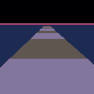
Hybrid rendering
The track is rendered from the the farthest to the closest road block compared to a camera, with weak perspective projection. This way, a 3D world is projected on a 2D screen.
projection x = 3D X / 3D Z
projection y = 3D Y / 3D Z
I did not use matrix projection because it have a cost. I try to code only what is necessary. Also, there is no rotation for the track. We project in 2D the 4 “vertices” of each road block. At this point we have coordonates for a 2D polygon. It is drawn with a rasterizer which fills triangle. I ended up with the 163 tokens one from @p01 which is fast and light. Later I used another function from Freds72 which have subpixel precision. Before all, I used the rasterizer from Alone In Pico 8.
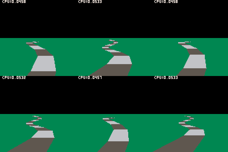
By applying a cos or sin function to X and Y world coordonates, and making the camera translate on Z, we obtain the following result (Note the little CPU cost <5,4%):
Below there is an excerpt focusing on road drawing block by block. I carefully make each vertex to be computed once. So for each road block, only 2 vertices are computed. The first iteration of the loop doesn’t draw anything, it has to wait for the 2nd iteration to have 4 vertices.
function drawroad(cam,ird,p)
 -- calculating road
 local r,rn,v,vn,vz=
  nil,nil
 --render info
 -- first partial offset
 local irdn=ird+1
 local irdlast=ird+nb_rb-1
 -- ready to draw road
 for i=irdlast,ird-1,-1 do
  v,vn=road[i%#road+1],
       road[(i+1)%#road+1]
  vz,xl,xr,iy,ylgt=
   v.z+flr(i/#road)*trklen,
   v.x-56,v.x+56,v.y,
   lerp(v.y,vn.y,0.5)
  -- clip
  dz=max(vz-cam.z,7)
  prc=(cam.z+7-vz)/rdz
  -- clipping
  if dz==7 then
   --interpolation
   xl=lerp(xl,vn.x-56,prc)
   xr=lerp(xr,vn.x+56,prc)
   iy=lerp(v.y,vn.y,prc)
  end
  -- current part
  fct=scale/dz
  r={
   x1=cx+fct*(xl-cam.x),
   x2=cx+fct*(xr-cam.x),
   y=cy-fct*(iy-cam.y),
  }
  -- drawing road
  if rn~=nil then
   -- drawing triangles
   otri(r.x1,r.y,r.x2,r.y,rn.x1,rn.y,v.c)
   otri(rn.x1,rn.y,rn.x2,rn.y,r.x2,r.y,v.c)
  end
  -- next
  rn=r
 end
end
Half-pipe system
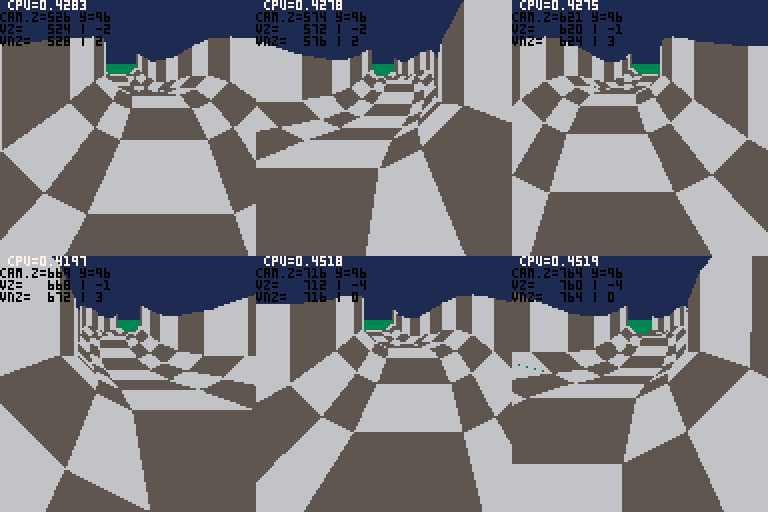
So, now that we can draw a straigth road, with no rotation but with a potentially different altitude for each road block, and that we are not constraint by shapes thanks to the polygon filling, we can imagine a way to enhanced the road. I had in mind that the road must be like a half pipe, to make the ships climb on the road when it turns. It is now possible ! One road block is composed of 6 parts, each parts with a different altitude. All the vertices are computed from the middle of the road (x=0,y=0,z=z road block), in the world coordonate system by changing x and y value for each vertex. Then those new vertices are projected on screen and here is the magic.

Then I wonder how many of these road block can pico8 draw ? So I made a full halfpipe to see how it is handled, and it perform well for 30 FPS. As I was aiming for splitscreen multiplayer, having the CPU under 50% was a good news, even if I also knew that I wasn’t drawing all I need for the race.\r\n
Road type
So what is the type of road block ? As you can see when playing, the road is not always in the same configuration, sometimes flat, sometime only right or left part of half-pipe and sometime both. This is the road type. The road type is a bit field that tell how the half-pipe is.
Value               256|...|16|8|4|2|1|
-----------------------+---+--+-+-+-+-+
2nd right elevation    |   |  | | | |X|
1st right elevation    |   |  | | |X| |
Normal flat road       |   |  | |X| | |
1st left elevation     |   |  |X| | | |
2nd left elevation     |   | X| | | | |
Start lane            X|   |  | | | | |
So a road type with full left elevation and 1 right is valued type=30 and looks like this :
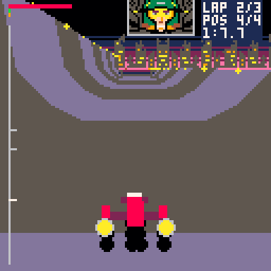
This value is set automatically when there is turns but it also can be force. That’s the case of the screenshot where the default for a straight road type is 4. I didn’t have enough pico8 token to put all the special road type I first wanted, but it is the game with pico8 !
The ship
Stacked Data
Ships are stored directly on the spritesheet. They are composed of 3 stacked layers, so editing a ship is really easy and fun, you just have to draw it. They are loaded in a array at the race init. You have the same kind of storage in Zepton and maybe other pico 8 cartridge. We also keep a shadow in a array, which is the 3 layers merged into one.
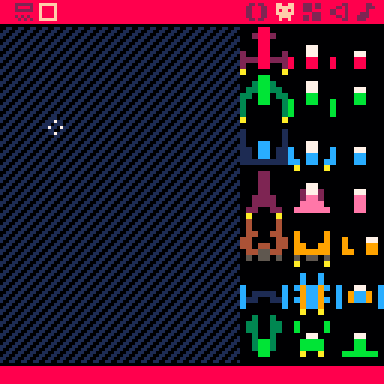
You can take a look at the implementation in the loadss function below. There is some extra information like width, height and mass compute from the pixels. You can also see that the shadow is half precision, to save some cpu when rendering.
-- loading a ship
function loadss(nbss,ss,sss)
 local m,xmin,xmax,zmin,zmax=
   0,8,0,8,0
 for k=7,0,-1 do-- y
  for j=0,7 do-- x
   local shad=false
   for i=2,0,-1 do
    c=sget(8*i+j,k+nbss*8)
    if c~=0 then
     v,shad=
      {x=j-4,y=i-1,z=4-k,
       oz=4-k,c=c,pat=0},
      c~=10
     m+=1
     add(ss,v)
    end
   end
   --half z
   if shad and k%2==0 then
    v={x=j-4,y=0,z=4-k,
     oz=0,c=9,pat=1}
    add(sss,v)
    xmin,xmax,zmin,zmax=
     min(v.x,xmin),max(v.x,xmax),
     min(v.z,zmin),max(v.z,zmax)
   end
  end
 end
 -- /5 because half_width*scale
 local si=ship_info[nbss+1]
 si.mass,si.width,si.height=
  m,(xmax-xmin)/5,(zmax-zmin)/5
end
Rendering
As we always see ships from the back when playing, we carefully load them from front to back, so they can be draw without sorting them and this saves a lot of cpu. The projection is the same that the one used for the road vertices (weak perspective projection).This projection is applied for each voxel. Another important feature we need to render ship is rotation, on multiple axis, because of half-pipe. The ship has the same rotation for all the voxels, so I compute one rotation matrix (I use a euler angles), one per ship and per frame. Then I apply the matrix to all the voxels. In splitscreen, this is done only once too. Here is the calcrotmat function, you can see that pitch, yaw and roll may not be standard, but I messed up to early with axis name to change them.
function calcrotmat(rot)
--pitch x yaw y roll z
local cosa,sina,cosb,sinb,cosc,sinc=
 cos(rot.z),sin(rot.z),
 cos(-rot.y),sin(-rot.y),
 cos(rot.x),sin(rot.x)

local axx,axy,axz=
 cosa*cosb,
 cosa*sinb*sinc-sina*cosc,
 cosa*sinb*cosc+sina*sinc

local ayx,ayy,ayz=
 sina*cosb,
 sina*sinb*sinc+cosa*cosc,
 sina*sinb*cosc-cosa*sinc

local azx,azy,azz=
 -sinb,cosb*sinc,cosb*cosc
return {xx=axx,xy=axy,xz=axz,
 yx=ayx,yy=ayy,yz=ayz,
 zx=azx,zy=azy,zz=azz}
end
A bit later, I use the applyrot function to apply the rotation on a ship. This is done once in the _update function.
function applyrot(ss,m,sort)
 -- faster 0.02cpu but +30 tokens
 local xx,xy,xz,
  yx,yy,yz,
  zx,zy,zz,rr=
  m.xx,m.xy,m.xz,
  m.yx,m.yy,m.yz,
  m.zx,m.zy,m.zz,
  {}
 for v in all(ss) do
  local r={}
  r.x,r.y,r.z,
  r.c,r.pat=
  xx*v.x+xy*v.y+xz*v.z,
  yx*v.x+yy*v.y+yz*v.z,
  zx*v.x+zy*v.y+zz*v.z,
  v.c,v.pat
  r.key=r.z
  add(rr,r)
 end
 -- z sort
 if (sort) shellsort(rr)
 return rr
end
Another little performance trick here is because rotation matrix is stored in a array, by accessing them once before the loop, we save 2% cpu because we no longer use array acces for each voxel.
Then, we have rotated voxels in world space, we can project them in the screen space, like we did for the road vertices. And as I’m lucky, I get this :
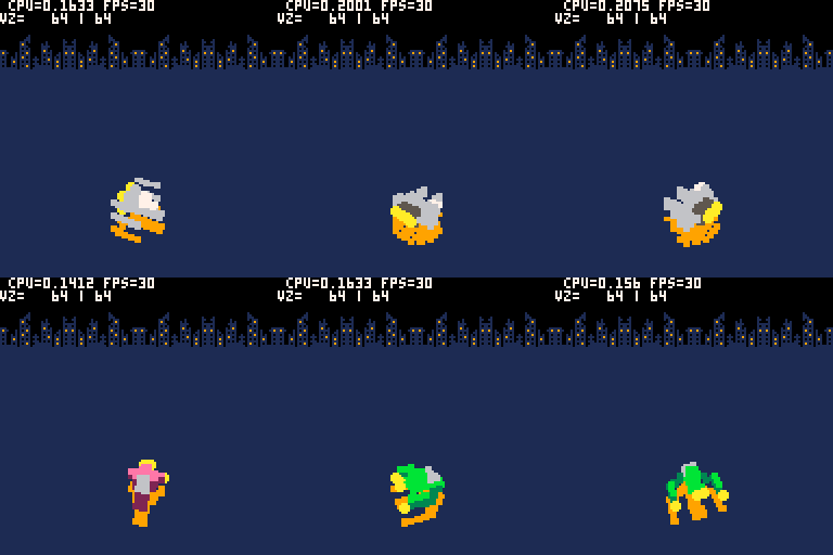
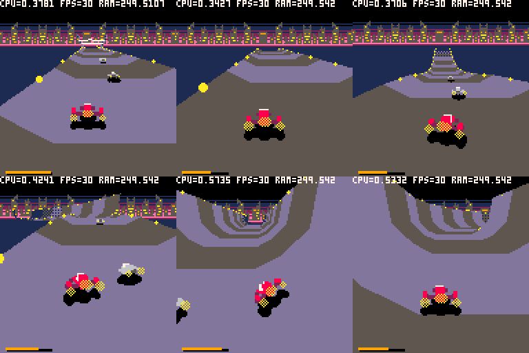
On this early screenshot, you can see an orange shadow. Actually, it is not a shadow but the light projected by the sustentation system. But it is difficult to “read”, so after some tries and twitter advices, I paint it black :D
Sur cette capture du début de développement, on peut voir une sorte d’ombre orange. Dans l’idée il s’agissait de la projection de la lumière émise par le système de sustentation. Mais ce n’était pas très lisible, et après quelques essais et conseils sur twitter, j’ai finalement laissé tombé et j’ai une vrai ombre noire.
In this case, we also sort the voxel on Z axis because the rotation is complete. But I only keep this sorting for the menu rendering, not in the game where the ship is always seen from behind.
Ships on the Road
As I mentionned earlier, the road is a straight array. I can even tell that the road is flat ! I handle the ship integration on a unfolded and flat road. Before rendering the road and the ship, the unfolded world is converted to the “real” world, the one with a half-pipe. At this moment, a rotation is applied around the ship Z axis to make it look like it fly parallel to the half-pipe part. I use a linear interpolation when changing angle to make the movement smooth.

So, according to the place the ship is placed on the unfolded road, a rotation on Z axis is added, and also gravity to make the ship “fall” to the half-pipe flat part. And here is the magic.
These tricks are the main structure of the rendering, all the details are integrated in this unfolded straight road. This save a lot of cpu for the other feature of the game. For example, collision checking is made in 2 dimensions, on the flat road.
Here is an excerpt of the convert function
function convert_xflat_to_x(pos,decx,ytmp,rot,spdp,shipp)
 local xflat,cumx,cumy,newz=
  pos.xflat-decx,0,0,1
 pos.x,pos.y=pos.xflat,0
 -- for each road part
 for stp in all(rd_info) do
  if xflat > stp.fl then
   -- startx,y
   stx,sty=stp.sx,stp.sy
   cumx,cumy=stx+stp.dx,sty+stp.dy
   pos.x=decx+lerp(stx,cumx,(xflat-stp.fl)/stp.dst)
   pos.y=lerp(sty,cumy,(xflat-stp.fl)/stp.dst)
   newz=stp.rotz
   break
  end
 end
 -- keep rotation
 if rot~=nil then
  rot.z=lerp(rot.z,newz,0.25)
  newz=rot.z
 end
 if pos.yflat then
  pos.x=pos.x
   +sin(1-newz)*pos.yflat
  pos.y=ytmp+pos.y
   +cos(newz)*pos.yflat
 end
 ...
 -- gravity
 if spdp~=nil then
  local gx=sin(newz)
  spdp.x-=gx
 end
end
The other ship, the ones that are away from the one you control, are rendering the same. There is just one difference linked to the fact that the turns are “old school”, based on an offsets accumulation. This offset accumulation must be considered to place the ship on X axis. If not the other ships will be placed near the middle of the screen even instead of on the road, if the road turns left or right. This is well explained in the code incomplete website, so I’ll not tell more here.
I Hope you like this insight, if you have questions you can leave a comment Lexaloffle BBS
Have fun !
Ressources: